Oct 12, 2026Guides
Windproof Roller Blind Parts and Drawings, Explained
Explore the anatomy of a windproof roller blind across eight models: the cassette, side rails and bottom bar, and the exploded views behind each one.
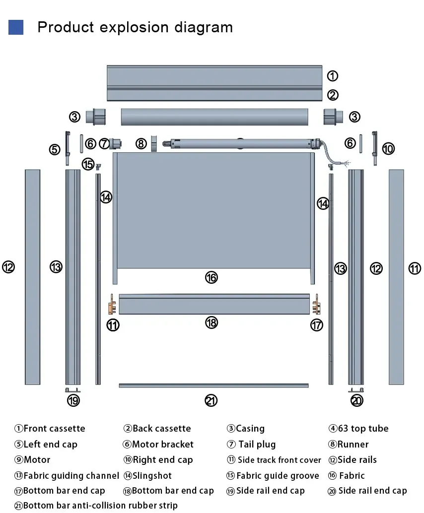
Every windproof roller blind is assembled from the same core parts: a cassette that houses the rolled fabric, aluminium side rails with guiding channels, the fabric itself, and a bottom bar. Each of the eight models carries its own drawing set on its product page. This article walks through the part names and the sheets so the drawings can be read with confidence before a specification is fixed.
The Parts in the Assembly
An exterior windproof roller blind works as one perimeter assembly rather than a set of loose parts. The cassette houses the rolled fabric at the top of the opening, and the cassette and the side tracks are aluminium alloy, so the fabric is held along its full drop and cannot pull out of its side channel. An aluminium alloy bottom rail keeps the lower edge stable across the span.
That full-depth retention is what separates a zipper-guided system from a standard drop or cable-guided arrangement, where the fabric edge stays free. The features page groups the same structure into three cards, one each for the casing, the wind side rail and the fabric, which is where the assembly is shown at a glance. Across the catalogue, eight models share this core structural logic, from compact residential sizes to wide commercial spans. Motorised models run on tubular drives with remote and Wi-Fi (TUYA) control; manual models use hand crank or cordless spring operation. The features page sets out the structure, and the zip-track explainer covers how the system holds fabric in wind.
Component Names and Where They Sit
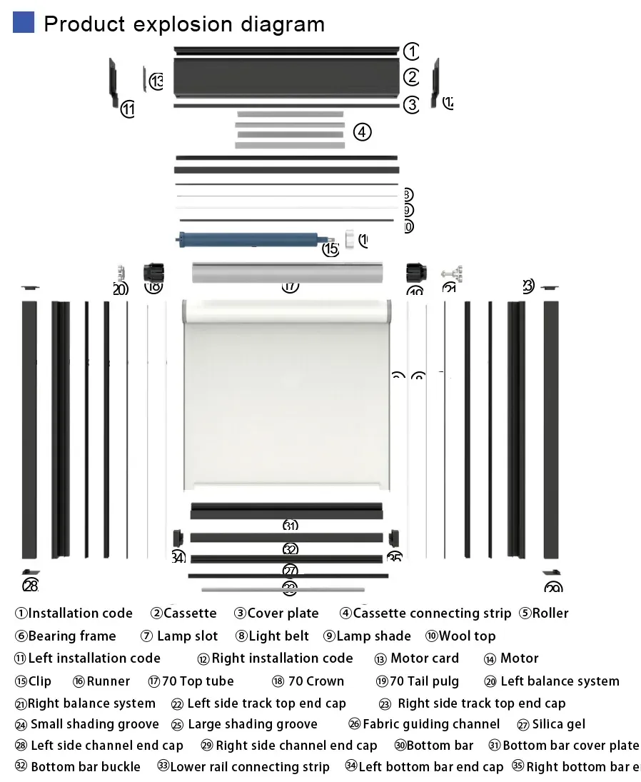
Reading an exploded view starts with the part names. On the product pages, each unit is shown broken down into its components, and the ZT90 drawing spells the list out in full: front and back cassette, Ø63 top tube, left and right end caps, motor bracket, runner, side rails with fabric guiding channel, fabric, and a bottom bar with anti-collision rubber strip. That list is a full inventory of the unit in one picture, from the housing at the top to the strip that sits at the lower edge.
The same names recur across the range, because every model works to the same arrangement: a cassette at the top, rails down the drop, fabric travelling inside them, and a bottom bar at the lower edge. The remaining labels, end caps, motor bracket, runner and top tube, sit inside the cassette assembly, and the drawing marks where each one goes. Read the cassette group together: those are the parts the rolled fabric and the drive run within.
The fitting guides add a second vocabulary for the parts a site team handles: side rail covers, guide strip, end cap assembly, expansion rubber plug, and guide rubber strips. The side rail covers are the parts that go over the fixed rails, and the guide strip and rubber strips are the parts the fabric edge runs in. Seeing the two lists side by side is useful, because a drawing name and a fitting name can seem unrelated until the exploded view shows where each one sits. With every component labelled, the drawing works as a shared reference for the fitting team and the specifier alike.
The Drawing Set Behind Every Model
Each model page carries its own drawing set rather than a generic sketch. The sheets are grouped under two headings: Construction and Specifications, then Profile and Product Information. A complete set contains:
- Exploded view: the whole assembly with every component labelled.
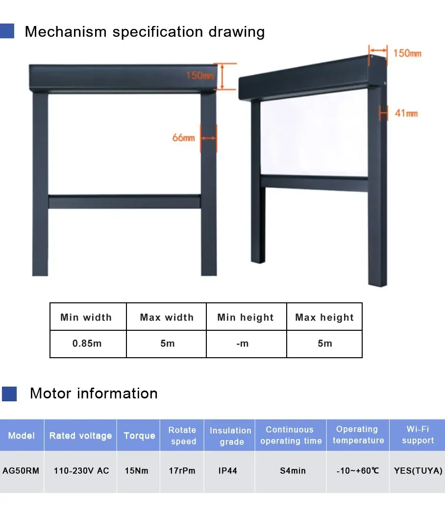
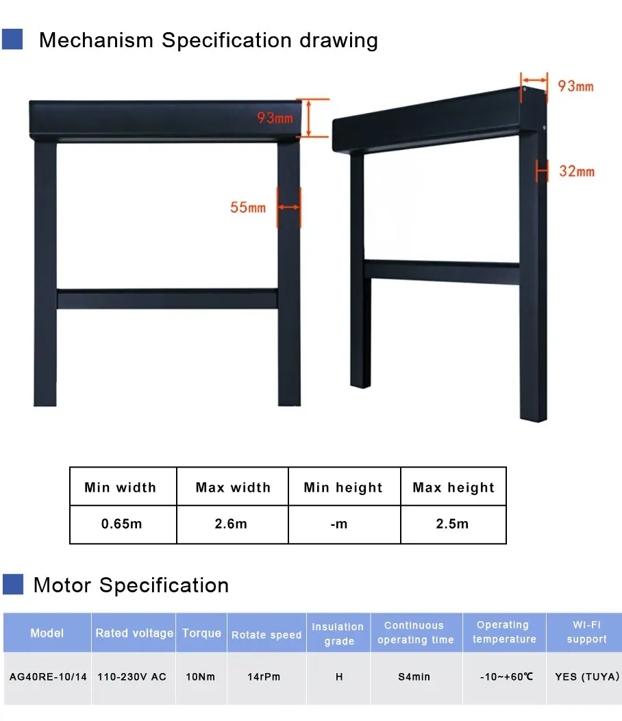
- Mechanism specification drawing: the assembly shown in elevation views, with dimension callouts.
- Size table: the model's width and height limits as the catalogue lists them.
- Motor specification: the drive information block on motorised models.
- Profile cross-section drawings: the section shapes of the cassette, side rail and bottom bar profiles.
- Catalogue product information table: the summary rows covering the model's track and bottom rail materials, fabric material and type, windproof grade and the stated fire-retardant standard.
Which sheets appear depends on the model, and the product page is always the reference for the version published for that unit. The range itself can be browsed from the products overview, which links through to model pages such as the ZT90 motorized windproof roller blind.
Reading a Mechanism Specification Drawing
The mechanism specification drawing is the sheet that answers fit questions. It shows the assembly in more than one view, typically a front elevation and a side profile, with dimension callouts marked on the views and a data block beneath them.
The views and the data block answer different halves of the same question. The front view covers the assembly across its width, and the side view shows the depth of the cassette and the rail profile. The data block carries the size table, which gives the model's width and height limits as the catalogue lists them, and on motorised models the motor specification sits alongside it.
The callouts let a specifier check clearance before ordering rather than after delivery. A wide model such as the ZT180 large size motorized windproof roller blind carries callouts that describe a larger envelope, which is the kind of envelope dimension a facade plan needs early. The sheet is a layout document for planning, and the size table is the part of it that a dimension check runs against.
Why Specifiers Ask for the Drawings
Each sheet answers a different question at specification stage:
- The exploded view is the parts reference: it shows what the assembly contains, so a buyer can see the components behind a model name.
- The mechanism drawing and size table are the fit check: they show the envelope a model needs, which is what a facade or pergola plan is drawn against.
- The profile cross-section drawings show how the rail and cassette sections meet the fixing surface.
- The product information table carries the materials and stated properties rows, which are the lines that go into a project schedule.
Read together, the sheets answer the two questions that stall an order: what arrives, and what it needs. The part list behind the exploded view is what a delivery is checked against, and the size table is what the opening has to agree with before production is booked. That is why the drawings are worth reading at specification stage rather than after the order is placed.
Check the product page or ask us when planning a specific frame or reveal. The drawings are product documentation, read for layout and planning purposes; where a project needs verified performance data, that is a separate conversation with the team rather than something the layout sheets carry.
Parts and Drawing FAQs
What does the exploded view label?
Every component in the assembly, each with its own number. The parts group in three bands: the cassette assembly at the top, the side rails and fabric down the drop, and the bottom bar with its rubber strip at the lower edge. The ZT90 sheet spells the full list out in one drawing.
Do all models use the same drawings?
Each model page has its own set. The shared logic is the same across the range, from the cassette and side rails to the fabric and bottom bar, but the drawings that document it are published per model and are not interchangeable between units.
Which sheet carries the size table?
On the mechanism specification drawing, beneath the elevation views. It lists that model's published width and height range, so a planned opening can be checked against it before ordering.
Where is the motor specification?
On motorised models it is part of the same mechanism drawing sheet, positioned with the size table beneath the views. It carries the drive information for that model, and the model page is where it is published.
Can I use the drawings for installation?
The drawings show component positions and clearances; they are not a step-by-step installation manual. Fitting follows the two illustrated step-by-step guides published on the site, one for rails-first mounting inside the frame and one for fixing outside the window frame. For anything specific to the unit in hand, check the product page or ask us.
Ask for the Drawings Before You Specify
Reviewing the drawing set before the facade is framed keeps later surprises out of a project. The sheets are published per model, so the sequence is simple: match the model to the opening, read its exploded view and mechanism drawing, and carry the size table and product information table into the project schedule. A model page consulted at design stage answers most layout questions without a second enquiry.
Send us the width and height of each opening, the preferred fabric transmittance and frame colour, and our team will confirm the configuration and provide a quotation. The site lists a shipment lead time of 7–15 days. For drawing questions or configuration checks, use the contact us page or email raymond@eziptrack.com.